Basic waveforms in pd vanilla
In this post, I try to detail how to create the “basic” waveforms used for subtractive synthesis using only Pd vanilla objects (without expr~).
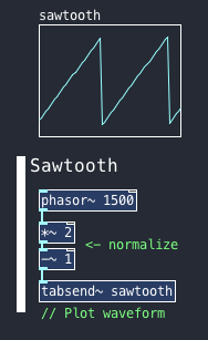
Sawtooth / Ramp wave
The Base for all our waveforms will be the phasor~ object.
Since its output is already a ramp waveform there isn’t much to do other than normalize it, because its values range from 0 to 1 when audio signals at their full amplitude should be bipolar ranging from -1 to 1.
To change the ramp for a sawtooth waveform, phase invertion is needed. This can be achieved by multiplying the resulting signal by -1.
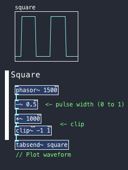
Square / Pulse wave by clipping
One way to make a square wave with a variable pulse width can be done by offsetting and distorting (clipping) a phasor~’s output.
The clipping stage here is similar to an if/else statement, where if the signal is more than 0 it will return 1, else it will return -1. This is thanks to the *~ 1000 multiplication that blows up any number to the extreme and clip~ -1 1 limits those values to -1 and 1.
The offset has a range of 0 to 1 and controls the pulse width of the waveform.
For example: when it is set to 0.5 the output of -~ will be 50% of the time on negative values and 50% on positive values, this results in a square wave.
If it’s set to 0.25, it will be 25% on negative values and 75% on positive values, this results in a pulse wave.
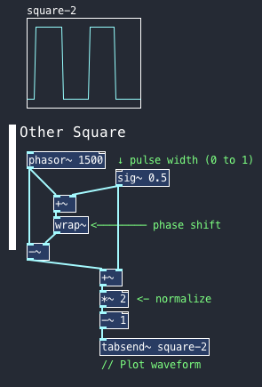
Square / Pulse wave by phase shift
Another way to make a square wave is to shift the phase of a parallel copy of the phasor~ and subtract it from the original (-~). This can be achieved by offsetting the signal with a +~ object and send that to a wrap~ object.
Depending on the offset is the amount of time, the signal will cancel itself, resulting in a square or pulse wave.
After that the signal gets normalized by summing the pulse width back into the signal (+~ 0.5), multiplying that by 2 (*~ 2) and subtracting 1 (-~ 1).
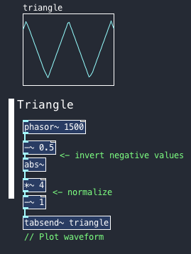
Triangle wave
One of the most simple ways to make a triangle wave out of a phasor~ is to invert half the cycle of its output.
This can be done by subtracting 0.5 to the phasor~’s output and sending that through a abs~ object which replaces negative values to positive values. The result is a triangle wave that ranges from 0 to 0.5.
Finally, normalization is done by multiplying by 4 (*~ 4) and subtracting 1 (-~ 1).
Implementation
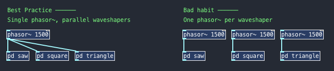
Looking at the conventional subtractive synthesizer structure, it is notorious to see that a single oscillator can produce several waveforms, but it only has one pitch control. That being said, it’s best practice using a single phasor~ object with all the wave shaping processes in parallel instead of one phasor~ per waveform. This way, we can achieve the “one pitch control, several waveforms” paradigm one can often see in synthesizers.
Another thing one can add to save some CPU is to use the switch~ object to turn off the DSP on the wave-shaper’s sub-patches that are not in use.
Aliasing
It is important to know these waveforms are not band limited, therefore aliasing will be present throughout the oscillator’s bandwidth, specially on the higher frequencies.
This sounds notoriously digital, but it can be reduced either by oversampling & filtering or other techniques such as polyblep.
Here are some libraries with band-limited oscillators: